As data center facilities increase in size, complexity, and energy consumption, new data center projects often require dedicated substations. When that is the case, the data center becomes an extension of the substation and is subject to its same inherent risks.
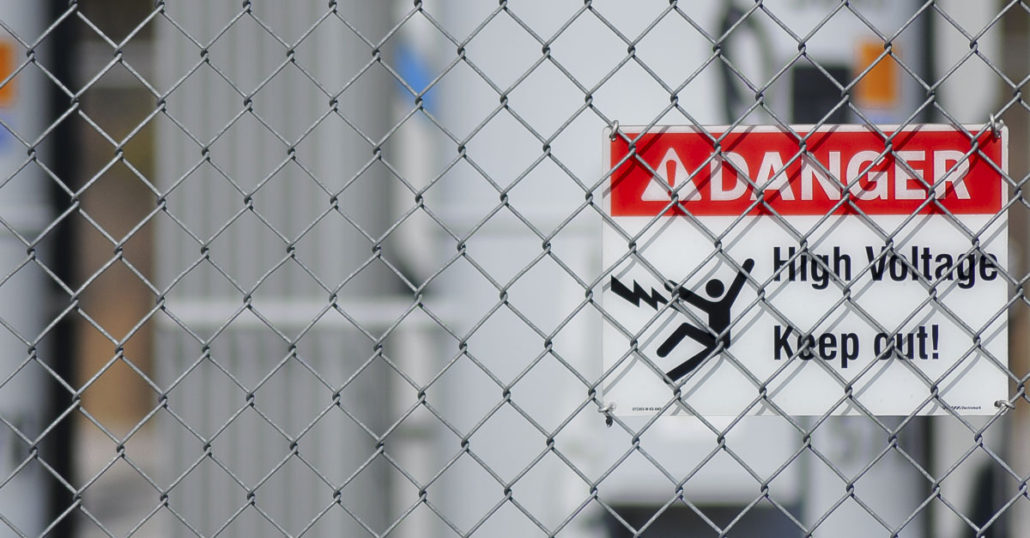
Regardless of who owns the substation, the risks to personnel and property remain the same – damaging or potentially lethal voltages caused by line-to-ground faults and lightning strikes.
So, how are these risks mitigated? A major safety component of a substation (or any facility for that matter) is the grounding system. A typical substation grounding system consists largely of a ground grid that is buried in the substation yard and bonded to all the equipment inside that substation, including the fence. It serves two purposes. The first is to lower the substation’s grounding impedance since we use the ground grid as our connection to earth. We do this because earth acts as a current-carrying conductor to dissipate noise and dangerous lightning currents and to conduct fault currents back to their source. In the case of a fault current, this allows the protective schemes to more quickly detect and isolate the fault.
The second and perhaps less understood purpose of the grounding system is to provide a common, equipotential voltage reference for structures, signals, and equipment bonded to it. This is important because under normal conditions the grounding system doesn’t conduct a significant amount of current, and its potential relative to remote earth remains at near zero volts. Also, everything connected to the grounding system remains at the same potential. Therefore, a circuit using ground as its signal (voltage) reference can communicate with other circuits also using ground as the signal reference. Under fault or lightning strike conditions, however, the grounding system must now conduct large currents and as a result, its voltage increases relative to remote earth, sometimes by several thousand volts. Under this condition, the grounding system still provides value by maintaining an equipotential between grounded structures, but a hazardous condition can develop where personnel can be shocked when touching a grounded structure that is elevated in potential while another part of their body makes contact with something (an ungrounded structure or earth) that has elevated to a different potential.
Unfortunately, a grounding system alone is not enough to fully mitigate these risks and prevent equipment damage or someone being sent to the hospital or the morgue. Have you ever noticed, for example, that a typical substation yard has a few common elements (crushed rock surface around the fence, gated areas and steel platforms for personnel to stand) that you don’t see at other types of facilities? Yeah, OK… maybe not. But if you did, you might have wondered why. Well, the answer is actually pretty simple; these elements help reduce the step and touch potentials that a person might encounter when a fault occurs somewhere – anywhere – on the utility power system.
Step and What???
Step and touch potentials are voltage differences that occur while the grounding system and earth are conducting current back to the source. These differences can be between a person’s feet when walking or standing near an energized grounded object (step potential), or between a grounded structure such as a fence or downspout and a person touching it (touch potential) while standing on the ground. It is the voltage difference, not the actual voltage, that causes current to flow through the body, and since it only takes about 100 milliamps of current to cause ventricular fibrillation, step and touch potentials can be deadly. And unfortunately, hazardous potentials are not limited by the boundaries of the substation, as they can occur a significant distance away.
Beyond the Yard
How do these hazards extend beyond the substation fence?
Data center sites are not typically treated like a substation when it comes to grounding. For example, there’s no campus-wide grounding system, no crushed rock surfacing around metallic structures, and the fences don’t typically have interwoven ground wires. By code, the substation’s grounding system is connected to the facility’s grounding system via the incoming power feeds, so when the substation’s grounding system becomes elevated in voltage, so does the facility’s grounding system. If the facility is physically located close to the substation, then both grounding systems elevate to essentially the same potential. Therefore, anything bonded to the facility’s grounding system, such as fences, downspouts, security cameras, gate operators, card scanners, light poles, lightning protection systems, and other outdoor metallic structures can expose the data center campus to these possibly lethal step and touch voltages.
For example, consider your security fence. The gate operator has power connections and grounding conductors that tie back to the facility’s electrical system, which is then tied back to the substation and its grounding system. Therefore, when the substation’s grounding system experiences a voltage increase during a fault, the grounding wire in the gate operator is also elevated to nearly the same voltage. And, since the gate operator is connected to the fence, the fence is also elevated. Left unprotected, the ground around the fence will be at a different potential relative to the fence, creating a hazard that can be quite shocking to an unwitting passerby who may learn the hard way about step and touch potentials. In a substation, this hazard is mitigated by running an underground conductor along the fence (sometimes both inside and outside the fence) and installing crushed rock as an insulating barrier between a person’s feet and the earth.
Don’t Stress – Assess
So, how do you know for sure that the people and equipment on your campus are adequately protected from a shocking incident?
The only way to be sure is to have a grounding specialist conduct a comprehensive assessment of your system and campus to determine if and where potential hazards exist. Unfortunately, many data center owners never even think about it.
For new facilities, a campus-wide grounding analysis should be performed during the design phase. Using soil resistivity measurements taken on site and the utility’s available fault current, grounding specialists model the interconnected grounding system, including the conductive objects installed on the data center’s campus to determine areas presenting step and touch hazards and to recommend grounding system design considerations and site-wide mitigation tactics.
For existing facilities, grounding specialists model the grounding system incorporating soil resistivity data collected on site and available fault current to verify the system is properly designed and installed, or to recommend any needed remediation.
For example, in a recent assessment for a large (500,000 sq. ft.) data center, HP&D specialists calculated the worst-case step and touch voltages around the site during a 100kV utility ground fault and then compared them to values that were considered safe. While we found that there were no step voltage hazards at the site, there was a safety issue associated with the touch voltages along most of the perimeter security fence and at all remote outdoor light and security poles.
As a result, we recommended adding a 4- to 6-inch deep layer of granite or asphalt in 4-foot ribbons along either side of the fence and around metallic gate operators to make these areas safer. We also recommended isolating portions of the security fence to reduce the shock hazard and suggested either replacing metal light poles with fiberglass or installing a rock, concrete, or asphalt surface around them to mitigate dangerous touch voltages.
Following an assessment, sophisticated testing allows you to validate the design, installation, and performance of your grounding system – even while the facility is energized. This testing helps ensure that your facility’s personnel and equipment are protected and that your data center safely achieves its desired potential.

Michael J. Kline, PE is an electrical engineer and preferred consultant for utility and energy companies, data centers, industrial plants, and critical facilities. He specializes in overvoltage analysis, grounding systems, lightning protection, UPS systems, PLC controls, integrated commissioning, and distributed generation interconnects. He began his career performing electric system studies and designing distribution substations for utility
Contact us to learn more or to schedule an assessment.