 The data center industry is exploring the benefits of bringing liquid cooling systems closer to the heat load (IT equipment) as opposed to the prevalent air-cooled systems. There is a growing interest in the industry to implement these new systems on a larger scale. Although our interactions with these systems have been on a small scale, our experience with multiple projects where this approach was implemented has provided valuable insights into the challenges and considerations for owners, design consultants, and commissioning agents.
Typically, IT equipment specifications are given to the design engineer requiring a specific amount of power and cooling. IT equipment technology often advances at a faster pace than mechanical cooling equipment. IT equipment selections can frequently change during project development and data hall population potentially impacting the commissioning and cooling requirements. Innovative technologies are being introduced that challenge traditional data center design and commissioning. This article will take a closer look at two of these technologies and the lessons we learned from testing them.
Vertiv XDM System
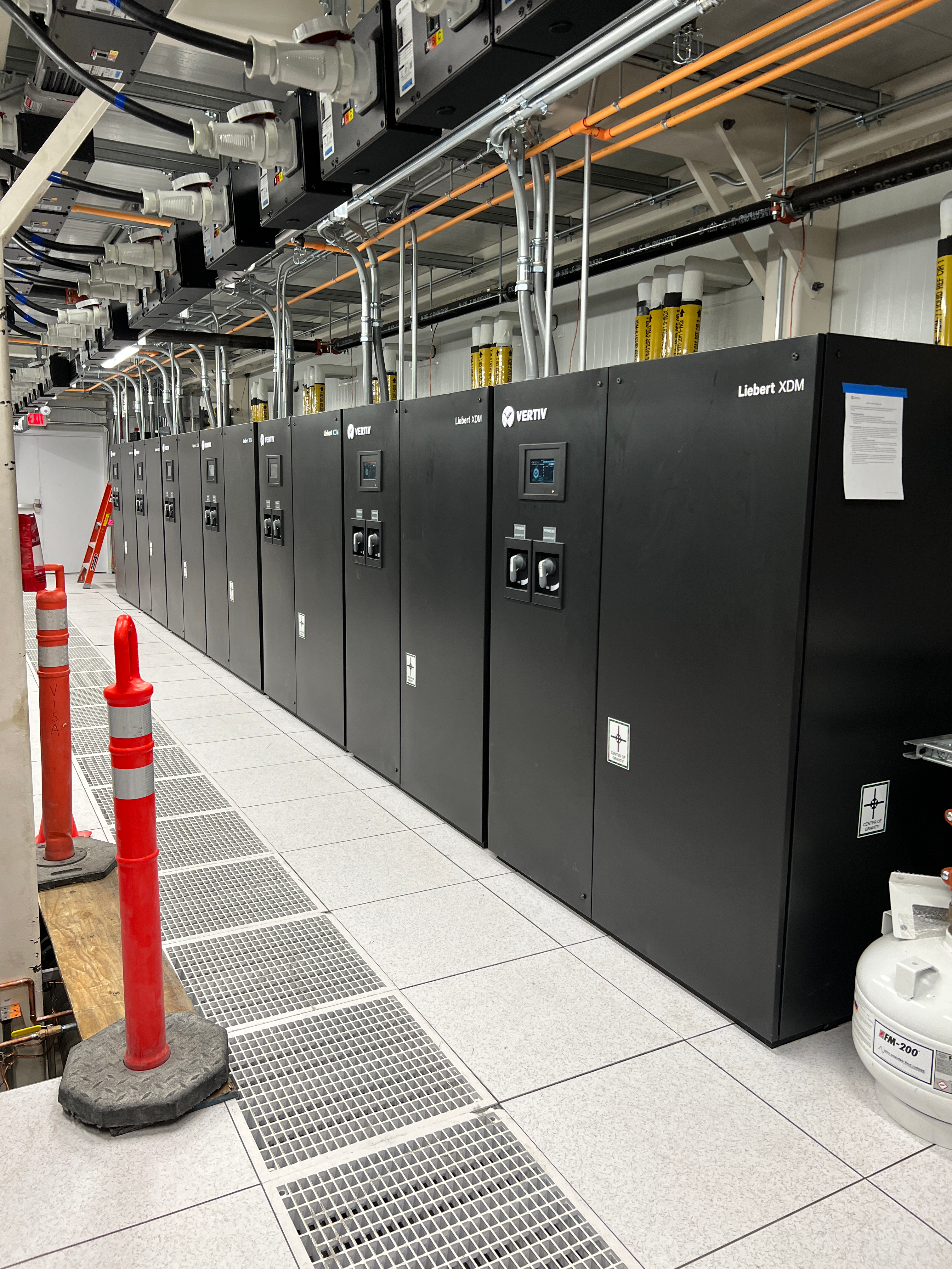
According to Vertiv, an XDM unit “is a split indoor chiller with integrated pumped refrigerant economization (PRE) designed to bring high-density cooling to targeted areas of air-chilled data centers, without the need for chilled water on site.” In a recent project for an existing data center, the XDM cooling system was installed by removing the standard raised floor and installing a containerized data hall and electrical modular containers. The packaged data hall consists of XDM units and passive coils on the rear of each IT cabinet. The XDM units are chilled water on the primary heat exchange side (evaporator) and DX (refrigerant) on the secondary heat exchange side (condenser) paired with MCV condensing units outside. The units are equipped with “iCOM” controls, as we see on other equipment, such as CRAHs from this same manufacturer.
- As with any innovative technology, several challenges were encountered during testing and operation highlighting aspects of the equipment design, installation, and operation, including:
The XDM equipment employs a draw-through type heat exchanger where the return water enters the heat exchanger first, then passes through the variable speed pump. This configuration does not remove heat from the pump itself, resulting in elevated enclosure temperatures due to the pump variable frequency drive (VFD) and compressors inside the cabinet. - Due to the draw-through heat exchanger pressure drop and required net positive suction head of the pump, a high (30+ psi) make-up water pressure was required.
- The system differential pressure sensors controlling the variable pump speed are located inside each of the XDMs. Typically, these sensors are located out in the piping system where the load changes take place. Putting them inside the unit near the pumps can lead to instability and delayed reactions to load changes.
- The XDM units are installed in a parallel configuration off the chilled water header to maximize load distribution between the units. The units are sequenced from the center unit, working their way out alternating sides. This internal configuration of the unit system controls means rotating the units to balance runtime is not ideal. Without this configuration, the load would take the path of least resistance and enter the closest unit causing an imbalance across all units.
- The most time-consuming issue to remediate was air in the system. The system was not equipped with enough automatic air vents, and with the chilled water coils being the highest point of the system, the coils collected air, impacting their cooling ability. Multiple automatic air vents were added on the chilled water headers, but as these were installed at the low point of the system, it took time to remove the air.
- The XDM units, like CRAHs, have redundant power feeds. In this application, the power feeds were not alternated initially, thus any upstream power outages resulted in all the units shutting down and restarting together when transferring to the secondary source.
- The operation of the chilled water control valves for each passive cooling coil is controlled separately by the building automation system. The operation proved to be slow resulting in a slow system response.
- The passive operating nature of the cooling coils installed in the rear doors of the IT cabinets requires the doors to remain closed for the heat exchange from the load to take place. After entering live operation, the owner discovered that the passive application of the chilled water coils could not satisfy the cooling requirements. Remediation required making the coils “active”, by adding powered fans to assist the heat transfer at the coils.
Vertiv XDU System
“Redundant pumps and power inputs ensure the Vertiv XDU is always doing its job while smart settings and teaming options ensure the precise temperature, flow rate, and pressure are continuously maintained to cool your IT environment as effectively and efficiently as possible.” – Vertiv
In an existing data center, the system was installed by removing existing CRAH units on a raised floor and reusing the CRAH chilled water connections inside a larger existing data hall. The new Vertiv XDU units consist of redundant tertiary pumps and heat exchangers supplying IT racks in a direct-to-chip cooling approach. The primary side (cold) of the unit heat exchanger connects to the existing building’s secondary chilled water loop/chiller plant. The secondary side (hot) is installed as a tertiary headered loop system for direct connection to IT equipment. The units are equipped with a new proprietary control package and unit-mounted HMI. The units are capable of being networked together and operated as a group for staging and rotation.
Like the XDM system, during commissioning, aspects of the unit construction and overall system design presented challenges:
- The XDU pumps are equipped with filtration strainers and must be selected based on the IT equipment. During testing, we experienced continuous dirty filter faults prolonging startup and testing. The initial filter media was selected with the assumption that the fluid would be the primary cooling media inside the IT equipment. This was not the case, and the filter media could have been much less aggressive. Additionally, it is important to note the filter media kept getting dirty due to the system construction (welding/brazing) and the load bank cleanliness; two issues that required additional time and effort.
- The system differential pressure sensors, controlling the variable pump speed, are located inside each XDU. Typically, these sensors are located in the piping system where the load changes take place. Putting them inside the unit near the pumps can lead to instability and delayed reactions to load changes.
- The XDU units have two pump control approaches, either system differential pressure or flow control. The flow control method proved to be the most difficult to test due to variable load and, in turn, variable temperature. The flow measuring devices in the unit are sensitive to temperature changes. Without a constant temperature present at the sensors, the flow measurement varies drastically. The system differential pressure approach, however, is much more stable and controls identically to other variable flow systems.
- The XDU heat exchanger’s primary side (cold) is equipped with a 3-way valve for controlling the discharge temperature on the unit’s secondary side (hot). This type of valve allows for constant flow on the primary side and should be accounted for when designing a new system or adding to an existing system.
- A cooling fluid make-up source must be provided, be it water or a glycol mixture, much like other fluid-based systems. From changing IT equipment to system maintenance, a make-up source is important to keep the fluid constantly engaged with the load. The XDUs can be equipped with an internal make-up pump and small fluid reservoir or have an external make-up source.
- IT equipment requires constant flow for continuous heat exchange, so uninterrupted flow on the primary and secondary sides of the XDU is necessary. The units have redundant power sources, although initially, the power feeds were not alternated. Without alternate power feeds, we recommend powering these units from a UPS-backed source. Additional consideration should be given to the primary side. This project employed an emergency pump in proximity to the XDU equipment that would start upon loss of flow from the main chilled water system.
Commissioning Considerations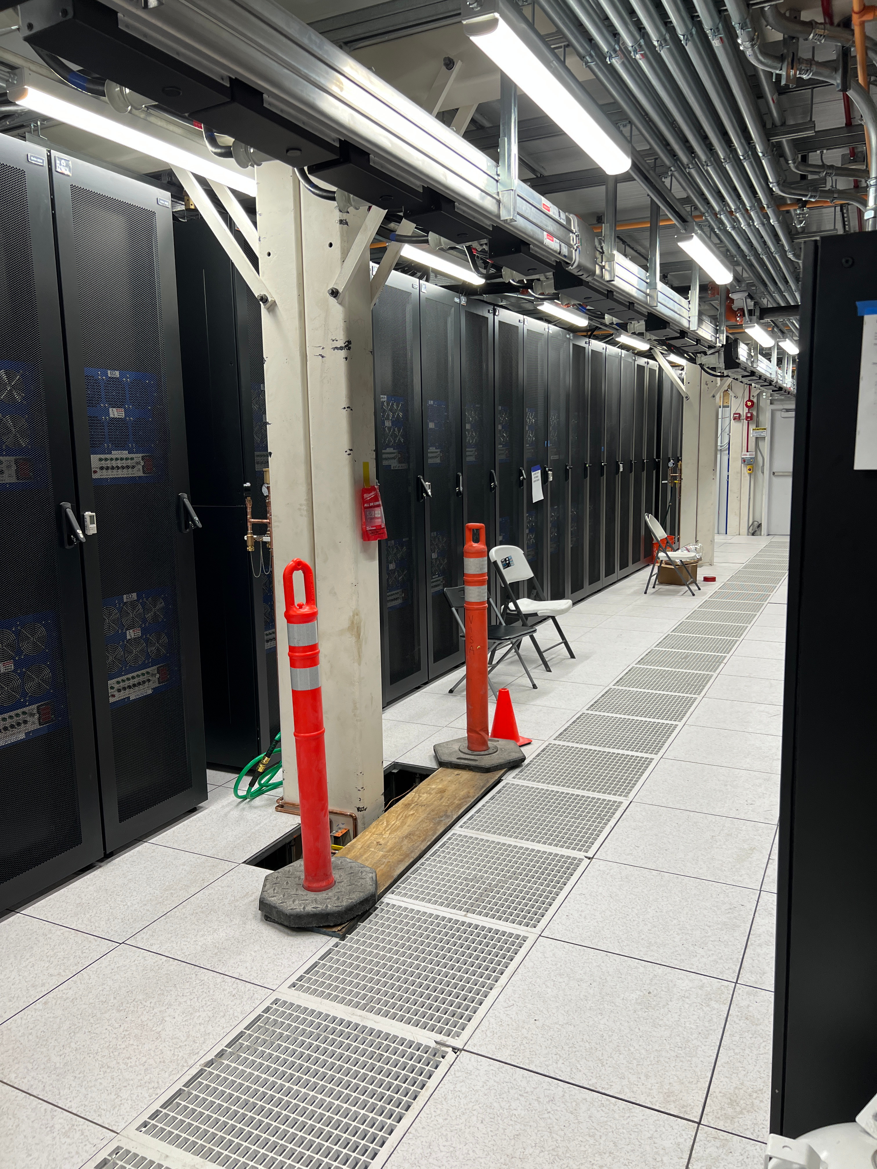
Every site, system, and component has its nuances and challenges. While commissioning scripts are a must, a good commissioning agent must be adaptable to the nuances of a given project, especially with a new product. Throughout the design, installation, and on-site commissioning process, many issues arise.
How to Commission?
This primarily defaults to the owner’s requirements and expectations, which should be communicated clearly before the project begins. Our approach is to test the systems and equipment as close to the ultimate purpose and end-use IT equipment as possible; thus, we prefer to simulate load by using load banks. The XDU equipment required water-cooled load banks, and the XDM equipment required rack-mounted resistive load banks (server simulators). This allows for all system components to be load-tested in conjunction with each other. To achieve this approach, multiple load banks are required.
An alternative approach is to load test mechanical systems and equipment more independently by using a boiler to test the chiller plant and a smaller quantity of load banks to simulate the IT load. Although this method would require far fewer load banks, the time to move load bank connections would need to be absorbed into the project schedule. In all cases, prior planning and preparation are needed. Additionally, the cost for rental or purchase and labor to install, connect, disconnect, and move load banks should be budgeted.
Availability of Test Equipment
Load banks can represent IT equipment, although not perfectly. To test these systems on a large scale, often a significant quantity of load banks is required, and due to the special nature of the required load banks, the availability in the industry is limited. Boilers are more readily available, although due to size and installation requirements, they are typically only capable of testing larger systems, such as chiller plants. The requirement for fully commissioning downstream equipment may require additional test methods.
Again, it is the owner’s discretion to specify the scope of work and the commissioning detail required. Based on those requirements, the approach should be tailored, evaluated, and planned in detail. Factors such as availability, cost, and schedule impacts need to be evaluated early in the project, along with other considerations, such as long lead times for equipment.
Keeping Your Cool
Bringing cooling closer to the heat load can potentially improve data center efficiency and significantly reduce water needs. Careful consideration and planning are required to ensure successful implementation. The most critical factor when choosing these systems is the end-use IT equipment. The long-standing approach by data centers to provide power and cooling at “X” capacity for IT to be populated later will not succeed for this new cooling technology. The IT equipment determines the cooling requirements, the system compatibility, and the commissioning scope. We strongly recommend selecting the IT equipment before the data center design and sharing detailed information with the design professional and commissioning agent.