Ground Grid Design & Soil
Electrical substations are built across the country, comprising a wide range of dimensions and voltages from 4.16kV up to 500kV. These substations are subject to electrical faults, of which 80% are single line to ground (SLG) faults. These fault currents can vary from a few hundred to many thousands of amperes.
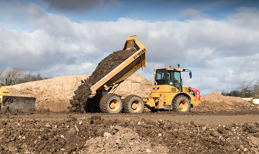
Knowing the fill type is essential when preparing a site for utility construction.
When designing an electrically safe substation, the cornerstone of any site is the native soil resistivity. Prior to design, Wenner tests are typically performed at or near the site to determine the soil resistivity with probe spacings from 1 to 400 feet or greater, depending on the dimensions of the proposed grid. These probe spacings result in both shallow and deep apparent soil resistivity values. At some sites, the large probe spacings are used to determine the depth of ground water. These results are employed to develop a soil resistivity model (typically a multi-layer model) to characterize the soil resistivity and thickness of the upper layer(s) and the deeper soil. The purpose of the site ground grid design is compliance with safety guidelines per IEEE Standard 80, including a suitable safety margin that allows for increases in fault current over the life of the substation.
Dirt Cheap
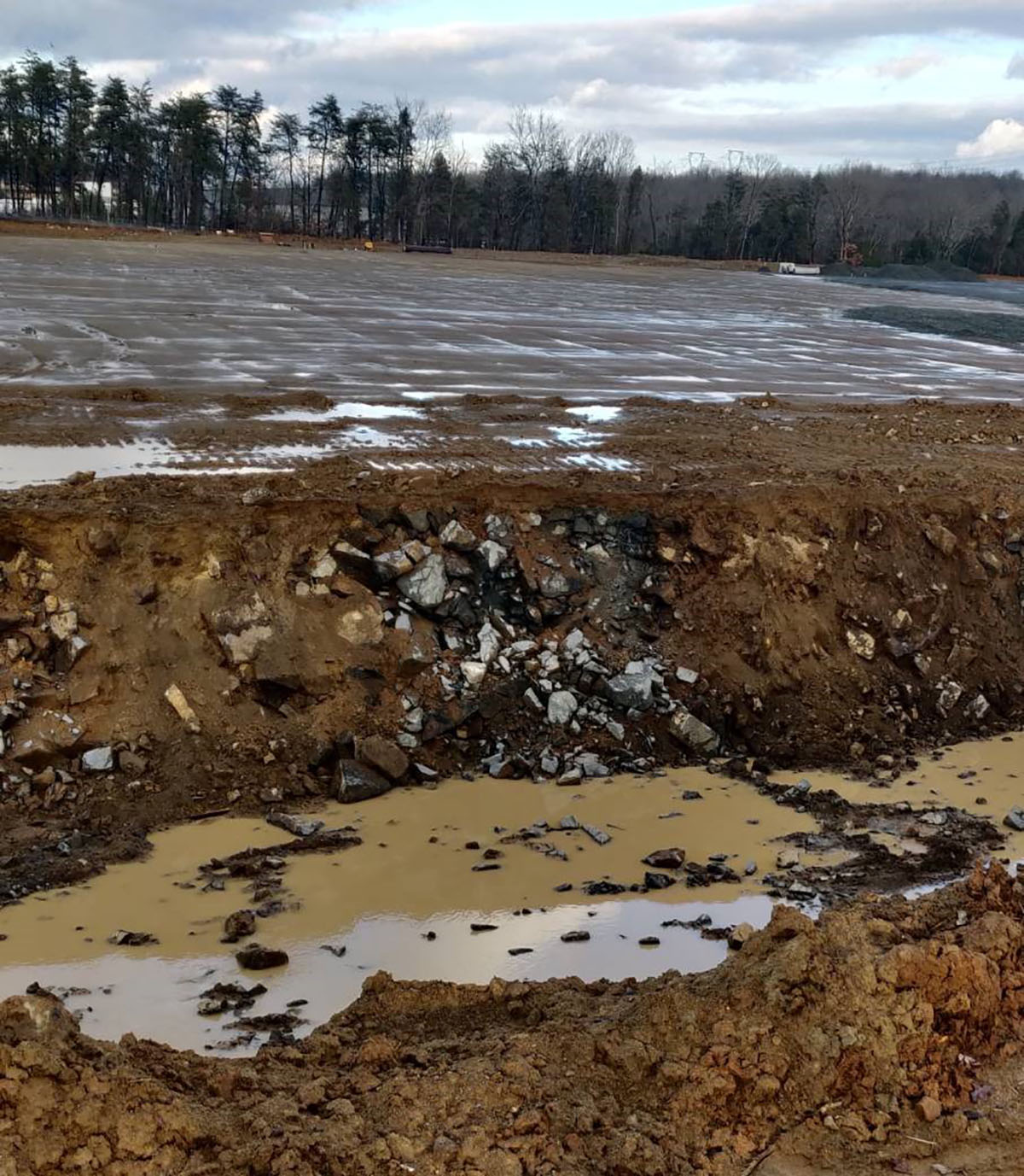
Backfilling the site with rock will impact the effectiveness of the grounding system.
Many new substation locations are faced with an unlevel site requiring extensive grading that either removes soil or adds non-native backfill in low areas. The primary goal during grading is to level the site as inexpensively as possible. We have seen sites where mounds of topsoil were removed and hauled away, exposing rocks, and other sites that have brought in loose-fill/rock. One site contained lots of large rocks, so rather than paying to haul the rock away, the owner brought in a large crusher and added the crushed rock mixed with the native soil back to the site. The problem with many of these grading solutions is they remove or alter the native soil – the soil that was tested for resistivity and used for the substation design to ensure safety.
At one site, the geotech contractor proposed to fill areas of the site with loose rock 12- to 18-inches in size. The proposed loose rock layer thickness was up to 8-feet of fill material followed with 5-feet of native soil and a 12-inch surface layer of crusher run stone. This fill material (of unknown resistivity) effectively places an insulating layer between the soils where the substation ground grid conductors are typically located (18- to 24-inches below grade) and the deeper native soil. In this example, longer ground rods would likely be required to penetrate to the now deeper native soil to ensure a safe and effective ground grid. A further complication is the difficulty in driving ground rods through or into this rock layer.
The function of ground rods is to allow the SLG earth currents to be dissipated into the earth. The number of ground rods required at a substation site is a function of the SLG fault current, as each ground rod can only dissipate up to 300 Amps of the earth fault current. This limit is required to prevent any local ground rod heating, which could have a drying effect on the buried soils and reduce the ground rod’s efficacy, and therefore, the entire substation’s safety.
If non-native fill must be used, options include:
- Purchasing a fill material with a tested, known resistivity value (more expensive)
- Using an unknown fill material (less expensive) and having it tested to determine the resistivity
- Crushing rock on-site (or obtaining finely crushed rock) and mixing it with native soils
- Modifying any added soil by mixing in ground enhancement material (GEM) or Bentonite to obtain the desired soil resistivity
In any event, a grounding system design review needs to be performed to make sure that the changes to the site’s soil do not result in an unsafe, non-compliant grounding system design.
Living in the Real World
From our experience, the addition of non-native soils or loose rocks beneath a substation pad will reduce the efficacy and safety of the designed ground grid. To ensure that a modified site still complies with IEEE Standard 80, the grounding design engineer will need to obtain additional details about the fill, the locations of the fill, and the areas of the pad with rock below to ensure that the balance between site ground resistance, site Ground Potential Rise (GPR) and the desired safety margins are not compromised.
To finalize the design, the site must be inspected after completion of the grading to identify the resistivity of the upper two feet of the substation pad – where the ground grid is to be installed – and to decide if that soil is acceptable or if it should be augmented with GEM or other low resistivity fill. HP&D has tested a number of sites where the upper soil has been compromised, very high ground grid resistances measured, and high touch voltages identified requiring remediation to comply with IEEE Std-80. While these sites may appear to be safe on paper, actual field testing verifies that many times, touch and step potential safety issues exist. When life safety is at stake, do you want to trust calculations alone?
For more information about substation fill and its effect on safety, contact us.