Grounding in electrical systems is a simple concept – theoretically. When it comes to testing, grounding quickly becomes more complicated. Grounding system testing is based on mathematical formulas comparing the system under test to “remote” earth and can’t account for real-world installations. Site testing is complicated by connections to other grounding systems and other grounded equipment that can influence the results, such as water and gas pipes, building steel, concrete footings, and any nearby buried conductive objects. Extremely difficult test sites include urban areas and campuses where remote earth simply isn’t available. You are trying to test and get an accurate value for the grounding system itself; however, you often wind up with a value that reflects a much larger system, typically the electric utility system, which gives you a false, very low value.

Real-world grounding system testing rarely matches the theoretical desired results driven by mathematical formulas
In simple terms, the intent of a grounding system is to create the lowest resistance path to “earth” to safely dissipate fault and lightning currents while protecting people and equipment. Due to the importance of a (hopefully) site-specifically designed and properly installed grounding system, it is common for a design engineer or owner to specify testing. As is often the case with testing, this requirement is just a checklist item on a project. Some form of grounding testing is performed, a report is delivered with an erroneous value, and no one is aware that the results are wrong.
Standards – What Standards?
References for grounding testing are difficult to find. The National Electric Code (NEC 70) Article 250.56 previously specified 25ohms or less as a target resistance for a single rod. This section was removed after the 2011 version; now, there is no mention of the desired resistance value for testing. IEEE Std 3003 Recommended Practice for System Grounding of Industrial and Commercial Power Systems covers how to ground components and systems in detail but doesn’t even mention testing. The InterNational Electrical Testing Association (NETA) summarizes testing with the following: “Perform fall–of–potential or alternative test in accordance with IEEE 81 on the main grounding electrode or system.”
The most definitive grounding system testing guide is IEEE Standard 81 Guide for Measuring Earth Resistivity, Ground Impedance, and Earth Surface Potentials of a Grounding System, which covers grounding testing in detail with many methods and derivatives discussed. It should be noted that this standard was developed for electrical utility substations and has a section labeled “Complexities” that states:
“The measurements of soil resistivities, ground impedances, and potential gradients of the earth introduce a number of complexities not encountered in other resistance, impedance, and potential measurements. In some situations, it might be necessary to perform several measurements to plot trends and analyze the situation. In addition, stray currents and other factors can interfere with the measurements. With the development and industrial growth adjacent to power substations, choosing a suitable pattern or location for test probes to make a resistance test is becoming increasingly difficult. The connection of overhead ground wires, buried water pipes, cable sheaths, adjacent railroad tracks, conveyor systems, and so on can affect the tested electrical circuit and introduce significant errors. To improve the accuracy of the measurement for comparison with calculated values, ground impedance measurements can be performed prior to interconnection of external shield wires, metallic pipes, and other external interferences.”
Unfortunately, testing prior to interconnection is extremely difficult, if not impossible, for existing installations.
IEEE Std 81 describes multiple methods of measuring ground impedance, including:
- Two-point method
- Three-point method
- Staged fault tests
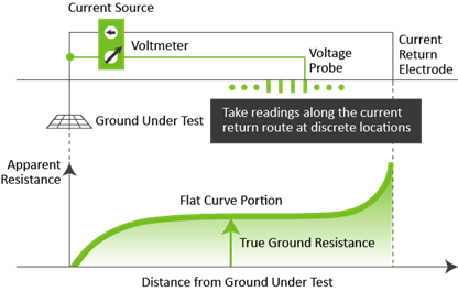
- Fall-of-potential (FOP) method
- 62% Rule (a shortcut of FOP)
- Slope method
- Clamp-on/Stakeless method
- Computer-based grounding multimeter
For the FOP method (the most commonly specified test method), IEEE states: “Additional limitations of the FOP method prevent it from yielding a true impedance value,” and “Only adequate for small completely isolated systems.” Unfortunately, most specifiers and those performing the testing and reviewing miss or misunderstand this caveat.
Real-world grounding system testing rarely matches the theoretical desired results driven by mathematical formulas
Specifications Need Not Apply
A typical commercial or industrial site testing specification includes the following:
- After installing the grounding system but before permanent electrical circuits have been energized, test for compliance with requirements.
- Inspect physical and mechanical conditions. Verify tightness of accessible, bolted electrical connections with a calibrated torque wrench according to the manufacturer’s instructions.
- Test the completed grounding system at each location where a maximum ground-resistance level is specified, at service disconnect enclosure grounding terminal, ground test wells, and individual ground rods. Make tests at ground rods before any conductors are connected.
- Measure ground resistance no fewer than two full days after the last trace of precipitation and without soil being moistened by any means other than natural drainage or seepage and without chemical treatment or other artificial means of reducing natural ground resistance.
- Perform tests by the fall-of-potential method according to IEEE Std 81.
This generic and common testing spec doesn’t address the site size, conditions, location, or appropriate test procedure, and it requires the test personnel to have extensive knowledge of grounding system testing to get accurate measurements. Even large electric utilities sometimes use a similar test requirement even though IEEE Std 81 admits that the FOP method does not apply to large, complex systems.
Hire an Expert
Grounding system testing has a steep learning curve as test personnel must be knowledgeable about the test location, test requirements, applicable standards (particularly IEEE Std 81), and the common issues and pitfalls of the various test methods. With subject matter knowledge, the tester can discuss the testing specification versus the site conditions with the consulting engineer or owner to determine the appropriate test method and equipment. Unfortunately, a lack of grounding expertise means testing is carried out, a box is checked, and inaccurate results are submitted, leaving a site vulnerable with a potentially unsafe grounding system. Sophisticated software-driven grounding test equipment is available that helps overcome the issues with many test methods; however, this test equipment is still dependent on highly trained grounding specialists.