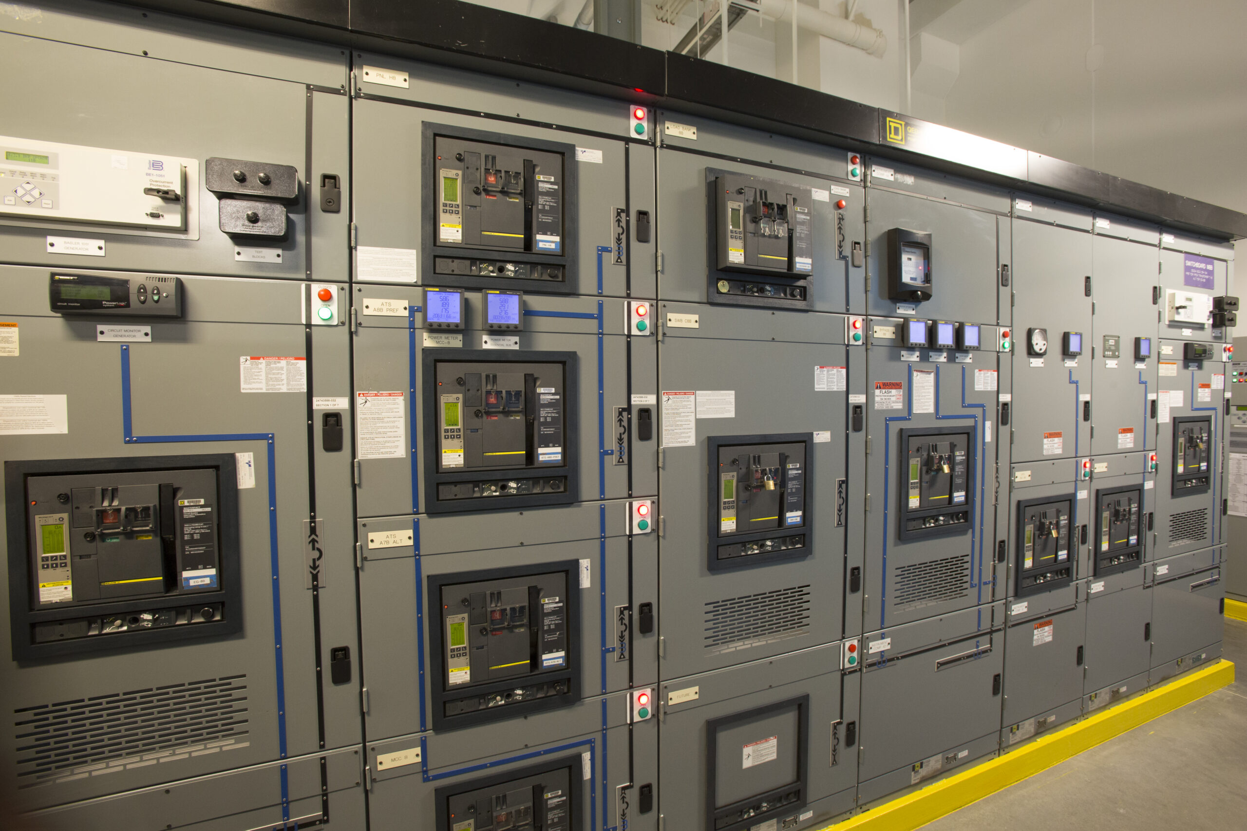
Courtesy of QTS Datacenters
The NEC requires over current protective devices (OCPD) to protect cables from overheating and catching fire which is achieved using long-time (LT) breaker settings. The NEC also provides guidance on ground fault (GF) and ground fault delay (GFD) settings. Additional settings on OCPDs include long-time delay (LTD), short-time (SD), short-time delay (STD), and instantaneous (I), which can be adjusted and coordinated to protect personnel and equipment from dangerous fault currents.
If the only goal was to protect equipment and people, then all devices could be adjusted to trip instantaneously whenever a fault is detected. The problem is miscoordination; this occurs when a breaker upstream operates instead of the breaker closest to the fault, and a wider outage than necessary occurs. A balance is needed between protecting equipment and people and maximizing the facility’s uptime; that is, coordinating for maximum uptime versus having a lower arc flash incident energy (AFIE). Unfortunately, these two goals can be mutually exclusive – meaning the emphasis can be on one or the other but not both.
In addition, different protection/coordination strategies are applied to different types of facilities. HP&D has performed and reviewed short circuit, coordination, and arc flash (SCCAF) studies for many industries, including data centers, hospitals, manufacturing plants, high-rise office buildings, campuses, etc. Each industry has, or should have, its own coordination philosophy. For example, a manufacturing facility typically prefers a lower AFIE on equipment so maintenance personnel can troubleshoot equipment. In this case, upstream device settings are adjusted to lower AFIE so personnel can work in less personal protective equipment (PPE). A data center, however, would lean more towards maximum uptime, sacrificing for a higher AFIE. Unfortunately, in data centers and many other facilities, coordination philosophy is often overlooked during construction. When the facility goes live, no one realizes the device settings don’t match the client’s (or design engineer’s) intentions. Sure, a coordination study is performed, and settings are implemented, but does the coordination philosophy actually meet the facility’s criteria?
Once the facility goes live, it is often too late to make any significant changes to settings as owners fear dropping loads and causing outages. A specialized studies engineer needs to be involved early in a project’s lifecycle. It is critical to perform a coordination study, have it peer-reviewed, and confirm device settings prior to the data center or any facility going live.
Hood Patterson & Dewar was recently asked to review the coordination study for a well-known company’s enterprise data center whose uptime is critical to their success. This example shows how applying the wrong philosophy to a facility can leave it susceptible to nuisance tripping and vulnerable to unnecessary power outages.
Case Study: What’s Wrong Here?
Our review of this data center’s existing coordination study indicated their ground fault settings for the devices feeding power distribution units (PDUs) and remote power panels (RPPs) were set to instantaneous (no intentional delay). However, we looked deeper into the settings and noted that the short-time delay (STD) and instantaneous (I) settings were also set very low, implying these breakers will likely trip at the slightest power disturbance leaving this data center vulnerable to nuisance power outages.
In this client’s case, we explained the existing settings conundrum and recommended areas where they could adjust settings to build in some adjustment space – a way to raise some device settings downstream while still maintaining a well-coordinated electrical distribution system.
 Recommendation #1: Substations
In larger data centers (as in this case), there is medium voltage (MV) distribution equipment feeding transformers in 480V substations with a Main-Tie-Main configuration. Two possible settings adjustments need to be considered here. First, the MV feeder breaker (controlled by a relay) and 480V main breakers are in series, so the same load will be affected regardless of what device operates. We recommend setting these devices without any coordination between them. Second, the 480V tiebreaker was coordinated with the two mains. There is a very low probability of a fault occurring in this part of the system compared to the downstream PDUs and RPPs, where personnel constantly interact with this equipment. Typically, there is little interface with the upstream switchgear, and the likelihood of a fault occurring at this level (after commissioning) is very low; however, the consequences would be greater. The trade-off: If the main and tie are set identically (not coordinated) and a fault occurs on the load side of the tie, a larger portion of the system would lose power. In our opinion, this is a risk worth taking as we recommend adjusting the tiebreaker the same as the main breakers. Setting the MV feeder and the LV main to trip simultaneously will provide more coordination space at the PDU and RPP level. When we explain this coordination philosophy, data center owners often agree and prefer this practice.
Recommendation #2: UPS and PDU Breakers
We often see study engineers coordinating UPS bypass feeder breakers with the bypass breaker and the main breaker of the downstream switchboards that feed PDUs and RPPs. As with recommendation #1, these three breakers are feeding the same load, so why coordinate these? Occasionally, we see the UPS output feeder breaker selectively coordinated with the main breaker at the PDU. Again, these breakers are in series and serve the same load, so there is no reason to coordinate these breakers. We recommend that the breaker feeding the bypass be the coordinated breaker with the other breakers serving as switches. In other words, set the bypass breakers and PDU main breaker as high as possible, leaving lots of coordination cushion in case of a hiccup that could clear itself before a breaker needs to trip.
Recommendation #3: Arc Flash Considerations
As stated previously, coordinating for maximum uptime and arc flash considerations can be mutually exclusive; however, we propose that a balance can be achieved. If breaker settings are tweaked as suggested above, there is room for coordination with the breakers feeding PDUs and RPPs. In this example, there is a row of RPPs, and 75% of them have an AFIE of 1.2 cals or less, and the rest jump up to 25 cals or higher. This discrepancy exists because the IE at the 1.2 level trips on the instantaneous or short-time delay setting and the 25 cals RPP trips at the long-time setting; the only difference is the cable distance from the distribution panel feeding the RPPs. A 20-foot difference in cable length can change the available AFIE at a device to trip in the long-time region instead of the short-time region. Using the philosophy mentioned above will give room to lower the short-time setting one or two “clicks,” which would reduce the AFIE from 25 cals to 1.2 cals. In this case study, this lower setting is still higher than the settings in the original coordination study.
Experience Matters – A Lot
As with most commercially available software, anyone can license a short circuit, coordination, and arc flash hazard program. However, as seen from this case study, successfully applying this software requires years of experience to understand all the considerations and nuances that go into a well-coordinated electrical system, one that balances the facility’s needs, equipment protection, and personnel safety. Make sure you are working with a professional who specializes in this area, so you have the best chance of maximizing your uptime safely.