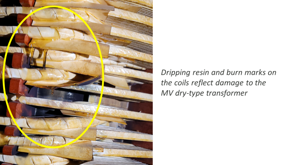
A manufacturing company was building a small data center fed by several 3000kVA, 4160/480V, dry-type, delta/wye transformers. Upon energization of one transformer from an alternate feed, a fault occurred, which caused its upstream medium voltage (MV) breaker to trip. The transformer was then re-energized from the primary feed, and facilities management personnel observed a flash. Assuming the breaker was the issue, the team inspected and tested the breaker. Finding no obvious problems with the breaker, the contractor videoed the transformer as they attempted energization again. This time, they recorded a flash in the coil of the transformer and, upon further investigation, saw burn marks. They decided to bring in a third party, Hood Patterson & Dewar (HP&D), to perform a root cause analysis and determine the path forward.
HP&D’s Site Inspection
Our investigation began with a site visit to inspect the equipment; interview site personnel and witnesses; gather all drawings, specifications, and equipment submittals; and review the energization video. The dry-type transformer in question has vacuum pressure impregnated (VPI) insulation. Our visual inspection noted two turn-to-turn faults at two of the coils. From experience, we knew three likely causes for the arcing: a lightning strike, a manufacturing defect, or a transient recovery voltage (TRV) issue. As no lightning was involved and a manufacturing defect seemed unlikely, we proceeded to investigate the possibility of a transient recovery voltage issue.
TRV occurs when MV vacuum circuit breakers (VCBs) interrupt inductive current at a point when the current is not at a zero crossing of either the current or voltage sinewave. The transient occurs when the current is extinguished and restrikes multiple times across the breaker contacts as they separate. Inductive currents are more likely to cause this issue because the zero crossing of the current sinewave does not coincide with the zero crossing of the voltage sinewave. The elevated voltage across the contacts causes current to flow quickly and repeatedly re-initialize, resulting in a voltage transient on the system. When the frequency of the induced transient and the transformer resonant frequency are in phase, the transient is amplified, causing stress to the transformer insulation, and potentially causing equipment damage.
We performed a transient overvoltage study to determine if the equipment could withstand the dielectric stress caused by the opening of the upstream VCBs. This study analyzes the switching transients at the transformer when inductive currents are interrupted (current chopping) with VCBs connected to lightly loaded transformers. Additionally, when the VCB and transformer are closer together, the transient voltages tend to be more severe. We performed this analysis and compared the results to the basic impulse level (BIL) rating of the medium voltage switchgear, VCBs, and transformers to verify that the equipment can withstand the dielectric stresses. When the transient voltage is above the BIL rating, the insulation is at risk of damage during breaker operations.
The Solution
When the study identifies this issue, a Resistor Capacitor (RC) circuit, known as a snubber, can be installed at the transformer to dampen the magnitude of the voltage transients and reduce their duration and rate of voltage rise. The ratings of the snubber circuit components must be tuned for the specific application to ensure effectiveness. A snubber circuit dampens the voltage transients’ magnitude, duration, and rate of rise (dv/dt). A surge arrester component provides basic overvoltage protection by limiting the peak voltage of the transient voltage waveform. However, the surge arrestor does not limit the rate of rise (dv/dt) of the voltage during the transient, nor does it provide any dampening. A surge capacitor, in combination with a surge arrester, slows down the rate of rise (dv/dt) of the voltage transient and limits the peak voltage. This combination does not eliminate the DC offset of the voltage during these transient conditions. Including a resistor with a capacitor and an arrester provides damping, reduces the DC offset, and minimizes the potential for current chopping.
In this case, our analysis found that the TRV exceeded the BIL rating of the 4,160V equipment. We recommended that an RC snubber with a resistance of 30 ohms and a capacitance of 0.50uF would reduce the transient overvoltage below the transformer’s BIL rating. The snubber circuit was installed between all the VCBs and MV transformers on site to protect the transformers’ insulation. While oil-filled transformers are generally less susceptible to this phenomenon, any MV dry-type transformer fed by a VCB should be evaluated, ideally at the design stage, to determine if a snubber circuit is necessary or to identify the appropriate equipment BIL ratings.


